
Link Installation
Wiring
Because aftermarket ECU installations are all customized, you'll need to purchase the appropriate length wiring harness and/or CANBUS hub for your installation from your ECU manufacturer, or wire something up yourself. WENDLab gauges use a standard DTM04-4P connector, which is plug and play with many aftermarket vendor wiring solutions. You'll need an open CANBUS port to connect to your WENDLab gauge. If you don't have an open CANBUS port, you may need to add a CANBUS hub or splitter to make one available.
If you're unsure what you need for your specific installation, please consult your tuner/installer.
Link
If you have a Link ECU, open the ECU case to expose the circuit board and verify the number of pins on the CAN connector as pictured below :

(Link G4X Pictured)
You can find the appropriate LINK CANBUS splitter/cable here : https://dealers.linkecu.com/products/accessories/can-and-tuning-cables
On some older Link G4 ECUs, you'll need a 4 pin JST to DTM CANBUS cable ( SKU 101-0198 ) and a 2m CAN Extension cable ( SKU 101-0214 )
On the newer Link G4X, you'll need a 5 pin JST to DTM CANBUS cable ( SKU 101-0197 ) and a 2m CAN Extension cable ( SKU 101-0214 )
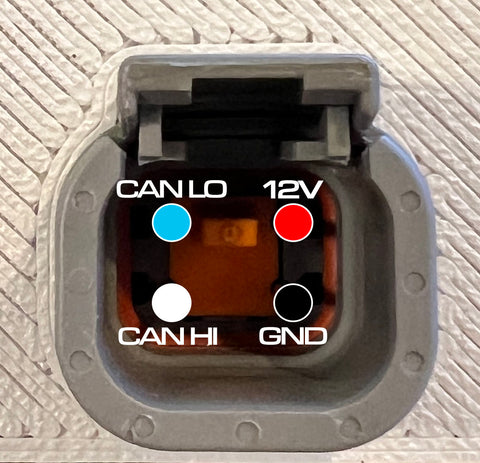
This is what the pins on the back of the device do. The socket is a Deutsch DTM04-4P that accepts a DTM06-4S plug.
The CAN HI and CAN LO pins are inverted from how the standard Link ECU DTM-4 plug is delivered. You can correct this by swapping the pins in the JST connector where it connects to the Link ECU.

PCLink Software Setup
Choose the "CAN Module" setting that matches the CAN port where you've plugged in the gauge.
Under CAN Setup, configure the ECU to "Transmit Generic Dash 2" on Channel 1 starting at CANID 1000. Set the "Transmit Rate" value to 10hz - 20hz depending on how frequently you'd like the gauges to update. 10hz is a good place to start.

( OPTIONAL -- if you have an ethanol content sensor or want to display boost and lambda target information) On Channel 2, configure the ECU to "Transmit User Stream 1" starting at CANID 1004

Then, under "Streams" configure Stream 1 to transmit the following Parameters:

Once you've got your gauge wired up and it powers on, it's time to set things up.
App Setup
Open the GaugeControl App
IOS : https://apps.apple.com/us/app/gaugecontrol/id6450934826
or
Android : https://play.google.com/store/apps/details?id=com.wendlab.gaugecontrol
The IOS and Android Apps look slightly different, but provide identical functionality :

and click "Find a Gauge" to search for devices over Bluetooth.

You'll see any WENDLab devices in Bluetooth range in the list that appears. Select your device from the list. When you want to reconnect later, you use the "slide to connect" slider to reconnect to the last device you used.

App features
From the main screen, the GaugeControl app allows you do select the gauge type and appearance of each display in your WENDLab gauge as well as update the firmware over the air to provide bugfixes and new features. If a firmware update is available, you'll see an "Update FW" button. If you're on the latest version, this won't appear. You can access an additional configuration screen in the top right hand corner via the = icon.

In the configuration screen, you can configure warning levels for multiple monitored parameters. If the ECU reports a value above the Maximum or below the Minimum configured value, you'll receive a warning indicator on the gauge. For single analog-style gauges, the digital readout will turn red and the background of the gauge will turn orange. For digital multi-gauge faces, the parameter that's gone in to warning state will turn red.

You can also choose your ECU type on this screen with the "ECU Mode" selector. Please confirm that the value displayed here matches your ECU platform if you don't see the gauge displaying ECU data.
The "Demo Mode" function displays a graphic on each screen.